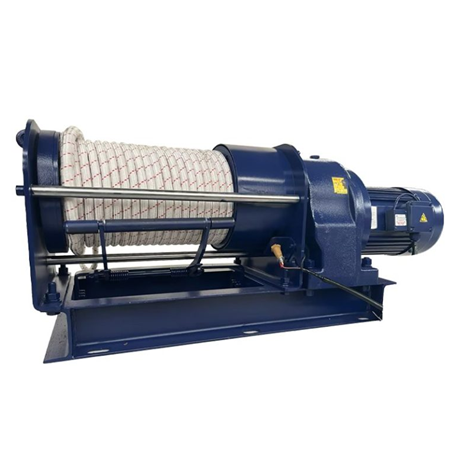
Dual-Motor Driven Winch | High Torque, Constant Speed & Redundant Safety | Long Travel with Level-Wind Options | KLD
When a single-motor winch is close to its torque limit, runs hot, or struggles to maintain smooth speed, moving to a dual-motor platform allows two motor/gear units to drive the drum together. This significantly boosts pulling capacity and system availability.
Combined with VFD (variable frequency drive) and PLC control, the system delivers soft start and soft stop, stable constant-speed segments, and real-time length and speed read-out. It is well suited for heavy-duty pulling, long-travel positioning and test platforms that demand both power and control.

02 | Core Value
Stronger output
Two motors running in the same direction provide higher torque reserves. For a given target speed you can run each motor at a lower individual load, reducing stress and improving service life.

Smoother speed
VFD closed-loop control with encoder feedback keeps the speed curve smooth and the constant-speed range easier to maintain. This reduces impact on tooling and fixtures and lowers rope wear.

Higher availability
The control strategy can be customized for each project, including master–slave logic, power distribution and derated operation modes. Under proper safety conditions, the system can keep running at reduced power during maintenance on one drive, improving overall uptime.
03 | Typical Applications
- Heavy-duty pulling
Bridge and municipal construction, hauling equipment uphill, positioning large components. - Long-travel reciprocating motion
Travel from tens to hundreds of meters where rope layering and consistent speed are critical. - Test and inspection lines
Constant-speed or constant-tension operation, with length/speed measurement and data logging. - Outdoor and near-shore environments
Corrosion-resistant design, dust- and water-resistant protection, capable of handling temperature swings and frequent washdowns.
04 | Typical Configuration Recommendations
Drive and control
Dual motors with VFD drives, coordinated by PLC/HMI. The HMI interface allows you to set speed and travel parameters, and check logs and alarms at a glance.

Drum and rope path
Drum diameter and groove pattern are customized according to rope diameter and travel distance. For longer strokes, the winch can be equipped with a level-wind device, rope storage unit and a tailored system of guide sheaves.

Braking and safety
Electromagnetic or fail-safe braking, upper and lower limit switches, emergency stop chain, overload/overcurrent/overtemperature protection. Audible/visual alarms and access interlocks can be added on request.

Materials and protection
Options include coated carbon steel or stainless-steel components. The electrical cabinet IP rating can be selected according to the environment, with optional low-temperature heating, dehumidification and corrosion-resistant fasteners for salt-laden atmospheres.
Interfaces and integration
PLC/SCADA I/O points are reserved. Encoder signals for length and speed can be output to the host system. The winch supports remote enable, interlocks and communication with multiple stations or work positions.

05 | Specification Range
- Pulling / lifting capability
From light duty up to multi-ton class, sized according to duty cycle and safety factor. - Line speed
Typical range is 6–20 m/min. Lower speeds with higher torque or higher-speed versions can be provided as required. - Travel distance
From tens to hundreds of meters. Multi-layer winding combined with level-wind and rope storage modules is used to meet capacity and layering requirements. - Rope type
Steel wire rope or synthetic rope, matched to the minimum bending radius and wear-resistance requirements of the guiding system. - Power supply
Three-phase 380–480 V, 50/60 Hz. Site power capacity constraints can be evaluated in advance. - Human–machine interaction
Pendant control, panel control or wireless remote. Encoders provide length and speed indication. HMI can be configured with recipes and user permission management.
06 | Comparison with Single-Motor Solutions
| Focus Area | Dual-Motor Driven Winch | Single-Motor Winch |
|---|---|---|
| Torque & redundancy | Higher torque, configurable master/slave and derated run | Torque and redundancy are more limited |
| Speed quality | Smoother speed; constant-speed range is easier to achieve | More affected by load fluctuations |
| Long-travel suitability | Level-wind and rope storage handled more comfortably | Drum capacity and layering are more restrictive |
| Maintenance impact | One motor can be serviced while running at reduced power | Maintenance windows are more rigid and disruptive |
07 | Key Points for Winch Selection
To size and configure a dual-motor winch correctly, the following information is important:
- Intended use
Pulling, lifting or positioning – briefly describe the working scenario. - Rated load (kN/ton) and duty cycle
S-class or the number of cycles per hour. - Target line speed (m/min) and acceptable fluctuation
Whether constant speed or constant tension control is required. - Total travel (m), rope diameter and rope type
Whether you need level-wind, rope storage or a system of guide sheaves. - Power supply
Voltage, frequency and site power capacity. Note any single-phase or peak current limitations. - Control philosophy
Pendant, panel or wireless control; whether length/speed measurement (encoder) is required; whether integration into PLC/HMI/SCADA is needed. - Environment
Indoor, outdoor or near-shore; temperature range; cleaning frequency; target materials and electrical IP rating. - Safety & compliance
Requirements for emergency stop, limit switches, overload protection, FAT, certificates or third-party witnessing. - Installation conditions
Foundation or support structure, rope exit direction, minimum bending radius, target delivery time and packing/transport requirements.
08 | Frequently Asked Questions
Q: How do the two motors keep their output in sync?
A: The PLC coordinates both drives. Two VFDs share the load based on real-time conditions and use encoder and current feedback for correction, ensuring consistent speed and pulling force.
Q: Will the load “run away” if there is a power failure?
A: The system is equipped with fail-safe braking, and the VFDs are set up with controlled deceleration curves. For back-driving conditions, the required braking torque is calculated and mechanical/electrical redundancy is added.
Q: Can synthetic rope be used instead of steel wire rope?
A: Yes. We optimize groove and guide design according to rope diameter and minimum bending radius, and apply reasonable de-rating if needed. Wear sleeves and appropriately sized sheaves are recommended.
Q: What about maintenance intervals and spare parts?
A: Routine work mainly involves bolt checks, lubrication and electrical inspections. We provide an annual inspection checklist and a recommended spare parts package, typically including brake units, limit switches, pendant/remote components and key wearing parts in the rope guiding system.