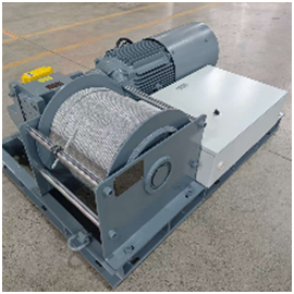


Customized Winch Design for a 20-Ton Underwater Experiment: How the Lifting System Was Determined

A single load figure does not define an experimental lifting system.
“The experimental load weighs approximately 20 tons.”
The practical question is how to choose the winch and system configuration.
A first assumption may be to specify a 20-ton winch, but the project conditions require a broader review.
In non-standard engineering, load weight is one input among several. Space, load movement, control accuracy, and the lifting path also determine the equipment solution.
The Chongqing University underwater experiment provides a clear case for this design approach.
The experimental items weighed approximately 20 tons. The real reasons this project required a customized design were the limited space inside the test pool, the possibility of load eccentricity, and the need for precise control.
Together, these conditions led to a customized winch and lifting-system design.
1. Project Overview: Customized Winch for a Laboratory Lifting System
The project partner was China Aviation Engineering Integrated Equipment Co., Ltd.
China Aviation Engineering Integrated Equipment Co., Ltd. is a subsidiary of Aviation Industry Corporation of China. Its main business includes equipment design and construction for companies within the group, as well as external design and construction projects.
The final user for this project was Chongqing University. The project involved underwater experiments.
China Aviation Equipment was responsible for the overall experiment project,while KLD handled the design and manufacturing of the lifting system.
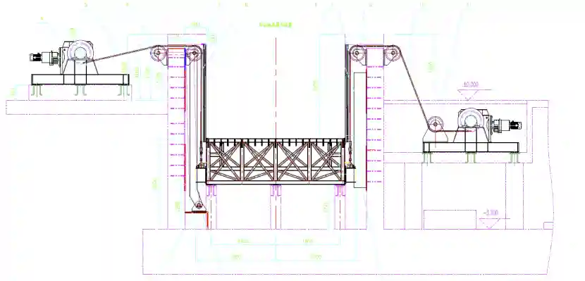
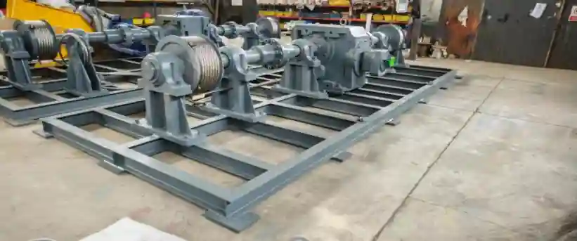
The laboratory lifting system was mainly used to raise and lower a grid-type platform inside the experimental pool. This customized laboratory lifting system was configured for an underwater experiment environment.
Experimental items weighing approximately 20 tons were placed on top of the platform.
At first glance, this may appear to be a heavy-duty lifting application.
The actual challenges came from the operating conditions.
2. Why Can’t “20 Tons” Directly Determine the Winch Model?
Although the experimental items were generally placed at the center of the platform, they could shift to some extent during actual operation.
The clearance between the platform and the pool wall was also very small.
This means:
- Load eccentricity may cause the platform to shift.
- The shifted platform may rub against the pool wall.
- In some cases, the platform could even become stuck.
For ordinary lifting operations, this issue may not need to receive such prominent attention.
Scientific experiments are different.
The operating space, control method, and motion accuracy of experimental equipment must match the specific experimental conditions.
Therefore, the core problem in this project was:How could the grid-type platform be raised and lowered more precisely within a limited space?
This is why the project ultimately adopted a customized lifting solution consisting of dual drums, fixed pulleys, and servo motors.
3. What Technical Requirements Did the Customer Specify?
According to the project information, the customer’s requirements focused on several areas.
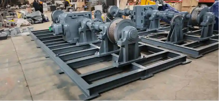
1. Dual-drum design
The lifting system used a dual-drum structure based on the actual operating requirements.
2. Fixed-pulley arrangement
Each rope was equipped with two fixed pulleys. These pulleys worked with the wire rope to create the required lifting-system layout.
3. Servo-motor control
The main output used a servo motor connected to the customer’s final control system to achieve precise control.
4. Matching error between the motor and gearbox
The customer placed particular emphasis on this issue.
The experimental site required high precision, and the platform was positioned close to the pool wall. Therefore, coordination among the motor, gearbox, and subsequent lifting movements was critical.
In other words, the customer did not need a simple “heavy-duty winch.” The requirement was a lifting system matched to the experimental operating conditions.
4. Technical Parameters That Shaped the Winch Design
The table show the design direction of the equipment.
| Key parameter | Drawing specification | Why it matters |
| Servo-motor power | 1,5 kW | Provides driving force for the lifting mechanism and supports the project’s precise-control requirements |
| Gearbox reduction ratio | 5944:1 | Reduces output speed and increases output torque through a high reduction ratio |
| Rated output torque | 54,494 N·m | Provides substantial output torque for the winch mechanism |
| Velocidad de la cuerda | 0.06–0.4 m/min | Low-speed operation supports controllability during the lifting process |
| Lifting stroke | 4 metros | Corresponds to the project’s actual lifting and lowering requirements |
| Wire-rope diameter | 12 milímetros | Matches the drum, pulleys, and overall lifting structure |
The winch configuration prioritized controlled low-speed movement over high-speed lifting.
The rope speed of 0.06–0.4 m/min, combined with a servo motor and a high reduction ratio, places greater emphasis on control at low speed.
That design corresponds directly to the project’s actual requirements.
Because the clearance between the platform and pool wall was small, any significant deviation could cause friction or even jamming.
For this type of laboratory lifting system, capacity is only one check. The lifting process also has to follow the required control method and movement accuracy.
Nota: Project information states that the experimental items weighed approximately 20 tons, while the technical drawing clearly specifies a winch lifting capacity of 2,000 kg. These figures cannot be treated as equivalent. Therefore, this article does not describe the equipment as a “20-ton winch.”
5. Why Use a High Reduction Ratio in a Servo Winch?
This is an important point that deserves separate explanation.
The table shows:1.5 kW servo motor + K- and R-series combined gearbox
Reduction ratio: 5944:1
The final rope speed indicates that the system was clearly not designed for high-speed operation.
The winch rope speed was only:0.06–0.4 m/min
For experimental equipment, this low operating speed has a direct benefit:It leaves more room for control and adjustment.
This is especially important when the platform is close to the pool wall. If the lifting process is too fast, the system has less time to correct any deviation.
Therefore, the reduction system was not added merely to make the motor rotate more slowly. It formed part of the overall drive solution.
Based on the available case information, the complete dynamic-design process corresponding to this reduction ratio cannot be derived. This article therefore does not extend into unsupported calculations.
6. Why Load Eccentricity Was the Main Design Risk
The most important design point was the possible load eccentricity, rather than the headline load figure or motor rating.
It would be:Eccentricity.
The case information clearly states that the experimental items were generally placed at the center of the platform, but some deviation was possible.
The platform was also positioned close to the pool wall.
If lifting continued after eccentricity occurred, the platform could rub against the wall or even become stuck.
For this reason, the customer placed particular emphasis on the matching accuracy between the motor and gearbox.
This requirement reflects an important characteristic of engineering projects:Equipment design must account for unusual conditions that may occur on site, not only normal operating conditions.
Therefore, the Tianheng Kairui engineering team completed calculation and verification before machining began
7. How the Dual Drums, Fixed Pulleys, and Servo Drive Form One System
The equipment functions as one coordinated system, with each component assigned a specific role in the lifting path and control sequence.
Dual drums
Address the structural layout of the lifting system.
Fixed pulleys
Work with the wire ropes to establish the lifting path.
Servo motor
Provides the driving force and supports precise control.
Caja de cambios
Transmits power and matches speed and torque.
Customer’s control system
Integrates the lifting equipment into the control system for the entire experiment project.
Therefore, the final delivery was not an isolated “winch.” It was a non-standard lifting system designed around the requirements of the experimental project.
This is why two winches with similar basic functions can require completely different engineering solutions.
8. Why Laboratory Projects Depend on System Matching
Ordinary material lifting can often follow this selection process:
Load → Speed → Stroke → Model selection
Scientific experimental equipment usually requires additional conditions:
Load condition
↓
Equipment space
↓
Lifting object
↓
Wire-rope and pulley arrangement
↓
Método de accionamiento
↓
Control accuracy
↓
Connection with the experimental system
This project provides a clear example.
Knowing only that the experimental items weighed approximately 20 tons was not enough to determine the complete laboratory lifting-system solution.
It was also necessary to understand:
- The structure of the platform
- The surrounding space
- Whether eccentric loading could occur
- The specific requirements of the control system
9. Which Projects Suit a Customized Winch and Non-Standard Lifting System?
Based on the design approach used in this case, customized winches, non-standard winches, and servo winches are more suitable for engineering scenarios where standard equipment cannot be matched directly.
Examples include:
- Scientific research equipment
- Laboratory lifting systems
- Underwater experiment projects
- Large-equipment lifting and lowering
- Equipos de automatización no estándar
- Specialized engineering lifting equipment
- Projects requiring precise operation
One point must be emphasized:
The need for customization is not determined solely by whether the tonnage is large.
If the site has unusual requirements concerning space, structure, control method, or operating conditions, non-standard design may be necessary even when the load is not particularly large.
10. Main Lesson: Select a Customized Winch by Operating Conditions, Not Tonnage
The original question can now be answered from the system conditions:Why does a 20-ton experimental load still require a customized lifting system?
The answer is clear.
The project had to address more than load weight.
It also involved:
- The lifting object inside the experimental pool
- The small clearance between the platform and pool wall
- Possible load eccentricity
- A dual-drum structure
- Fixed-pulley arrangement
- servoaccionamiento
- Low-speed precision control
- Matching accuracy between the motor and gearbox
- Integration with the customer’s control system
These operating conditions collectively determined the final equipment solution. They also explain why a customized winch was selected for the underwater experiment lifting system.
Therefore, when selecting a winch, customized winch, or laboratory lifting system, do not begin by asking: “Do you have a 20-ton winch?”
First clarify several key questions:
- What needs to be lifted?
- How will it be lifted?
- How much space is available?
- Could the load become eccentric?
- What lifting speed is required?
- What control accuracy is required?
- Must the equipment connect to an existing control system?
Only after these details are clear can a lifting solution suitable for the site be determined.
Conclusión
Equipment customization is often not intended to make parameters larger. Its purpose is to match equipment parameters to actual operating conditions.
In the Chongqing University underwater experiment project, the approximately 20-ton experimental load was only one background condition.
The factors that truly affected the lifting-system design were the experimental-pool environment, platform structure, possibility of eccentric loading, and precise-control requirements.
The final solution used dual drums, fixed pulleys, a servo motor, and a combined gearbox. Before machining began, the team calculated and verified the matching accuracy between the motor and gearbox.
For non-standard lifting equipment, a good solution is not the one with the largest parameters. It is the one that matches the operating conditions.
Pure mechanical logic. No sensors. No power supply. No control system
11. FAQ: Customized Winch Design for Laboratory Lifting Systems
Q1: Why can’t a 20-ton experimental load be handled by a 20-ton winch?
The weight of the experimental load cannot be directly equated with the lifting parameter of a single winch.
In this project, the experimental items weighed approximately 20 tons, while the winch technical drawing specified a lifting capacity of 2,000 kg. These are parameters at different levels. Therefore, it is incorrect to interpret them simply as “20-ton experimental load = 20-ton winch.”
Q2: Why did this equipment use a dual-drum design?
The dual-drum design was determined by the customer’s actual operating requirements.
The lifting object was a grid-type platform inside an experimental pool. The drums, wire ropes, and fixed pulleys had to be arranged as an integrated system according to the on-site lifting structure, rather than by using a standard single-drum winch.
Q3: Why were two fixed pulleys configured for each rope?
The case information clearly states that each rope used two fixed pulleys.
They worked with the drums and wire ropes to establish the complete lifting-system arrangement, ensuring that the equipment structure matched the actual operating method on site.
Q4: Why did this customized servo winch use a 1.5 kW motor?
The technical drawing shows that the equipment used a 1.5 kW servo motor with a brake.
The project required precise control of the experimental process. Therefore, the main output used a servo motor connected to the customer’s final control system.
The design focus was not simply to use a motor with greater power. It was to match the drive and control system to the actual lifting conditions.
Q5: What is the significance of the 5944:1 reduction ratio?
The technical drawing specifies K-series and R-series combined gearboxes with a reduction ratio of 5944:1.
Combined with the equipment’s rope speed of 0.06–0.4 m/min, this indicates that the system emphasized control during low-speed lifting rather than high-speed operation.
The case information does not provide the complete dynamic calculations. Therefore, no further design conclusions can be derived from this parameter alone.