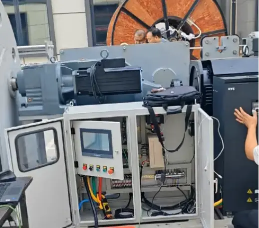


Getting a jumper back to the platform takes its own engineering. For an installation that retrieves people upward, a bungee recovery winch must manage a long rope path, controlled lifting and secure holding throughout the return movement. The recovery arrangement needs to fit the platform and the way the attraction operates.
KLD has developed a configuration for this application with a specified load capacity of 500 kg and a recovery travel specification of 155 m. Its design combines a single-layer grooved drum, rope pressing rollers, electromagnetic and hydraulic brakes, and PLC control. Each component has a specific job during retrieval.
For operators and equipment integrators, the selection process starts with the recovery route. Platform height, required rope movement and available installation space need to be established before the winch configuration is agreed. KLD's custom-engineered winches provide a starting point for discussing those application requirements.
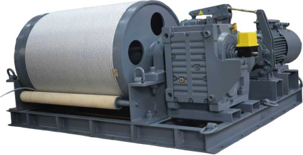
What a bungee recovery winch does
In the arrangement described here, the winch retrieves a suspended person after the jump and returns them toward the platform. The drive turns the drum through a reduction system, winding in the wire rope. The control system manages the commanded movement, while the brakes provide the specified stopping and holding functions.
That recovery sequence needs a clear definition. Where does retrieval begin? Where does the person finish the movement? How does the operator control the approach to the platform? These questions establish the operating task that the mechanical and electrical systems must support.
A tower installation and a cliff installation may need different mounting arrangements even when their recovery distances are similar. The rope route and access to the machinery also depend on the site. A layout drawing gives the supplier a more useful basis for selection than platform height alone.
Reading the 500 kg configuration correctly
The following values describe the KLD configuration discussed in this article. They provide a reference for a project enquiry; the final technical agreement needs to identify the equipment and operating conditions to which each value applies.
| Parámetro | Configuration specification |
| Specified load capacity | 500 kilos |
| Specified recovery travel | 155 m; confirm usable travel for the installation |
| Diámetro del cable de acero | 8 milímetros |
| Specified rope speed | 47 m/min; confirm operating speed profile |
| Rope winding arrangement | Single-layer grooved drum |
| Rope retention | Rope pressing rollers |
| Braking arrangement | Electromagnetic brake and hydraulic brake |
| Sistema de control | PLC control, with handheld remote control supported |
| Equipment weight | 850 kilos |
The load figure needs an agreed definition covering the intended recovery arrangement and attachments. Comparing it with a person's body weight does not establish the safety margin of the complete installation. That assessment requires the actual load conditions and system design.
Likewise, equipment weight is an input to installation planning. The mounting structure needs an assessment that covers the proposed machinery and its operating loads. Confirm what the stated weight includes before completing the structural design or planning delivery to the platform.
Planning recovery travel and rope speed
Start by drawing the complete rope path, including the drum, guides and recovery position. The required movement must account for the actual installation geometry. Confirm usable recovery travel separately from the total installed rope length and the rope that must remain on the drum.
For the 155 m configuration, ask the supplier to show how the proposed arrangement covers the required retrieval route. A platform's height above the ground does not, by itself, describe every section of rope or the full movement needed to reach the final recovery position.
Speed needs the same attention to operating conditions. The stated 47 m/min figure should be defined in the technical agreement, including whether it represents a maximum, nominal or average value. The agreed movement profile should describe acceleration, normal retrieval and the approach to the stopping position.
Operators also need a realistic view of the complete recovery cycle. Rope travel is only one part of that cycle. Reviewing the sequence with the equipment supplier helps establish where controlled movement and operator decisions are required, without treating a single speed figure as the time needed for an entire retrieval.
Single-layer winding and rope retention
A single-layer grooved drum gives the rope a defined winding path. In this configuration, the rope occupies one layer across the drum instead of building up successive layers. The groove geometry and available drum width therefore need to match the selected rope and required storage length.
The design also includes rope pressing rollers intended to help keep the wire rope seated in its grooves. Their arrangement should be reviewed together with the rope entry path and guide components. Correct winding depends on how the rope reaches the drum throughout the movement.
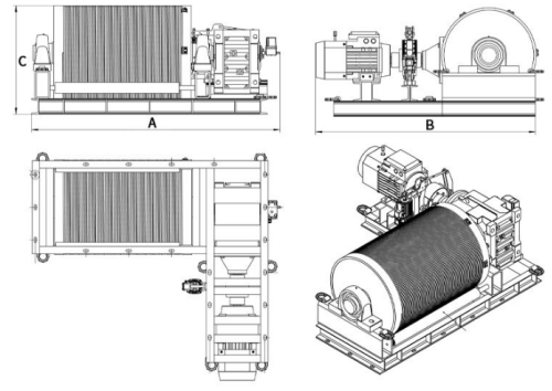
A large drum is part of the design approach to managing wire rope bending. Its suitability still depends on the rope specification and the rest of the rope path. Procurement documents should identify the agreed drum dimensions, rope construction and inspection requirements, with consistent terminology across the drawing and parameter table.
KLD bungee winch product configuration provides a related reference for the grooved drum and dual-brake arrangement. Confirm the configuration for personnel recovery explicitly when discussing a project.
Defining electromagnetic and hydraulic braking
This bungee recovery winch uses an electromagnetic brake together with a hydraulic brake. The technical review should explain where each brake acts and how the two operate during normal stopping, holding and the specified emergency conditions.
Two brake types describe the hardware arrangement. To assess its performance, the buyer needs the control sequence and verification criteria as well. Ask the supplier to document the intended response to power loss and an emergency-stop command, including the conditions under which that response will be tested.
The same review should cover brake inspection and maintenance access. A component that is difficult to reach can complicate routine work once the machinery is installed. Agree on service access while the mounting layout is still being developed.
Keep braking claims specific to the confirmed design and test results. Terms such as "immediate stopping" need defined conditions and a measurable acceptance method before they can describe the installed system's performance.
PLC control and the operator's recovery sequence
The configuration includes PLC control and supports handheld remote operation. These functions should follow the attraction's agreed recovery sequence, with clear commands and operating states that the operator can understand.
For example, a request for one-button operation needs an explanation of the actions that follow the command and the conditions that permit them. The technical agreement should also describe how the operator stops movement and what happens if remote communication is interrupted.
Confirm the required control location and visibility of the recovery route. Where the winch must communicate with other equipment, define the exchanged commands and status information before commissioning. Interface details affect how the complete installation responds during operation.
Training should address the delivered controls and the approved operating procedure. The presence of a simple remote handset does not determine the training needed for personnel recovery.
Preparing a project enquiry and acceptance plan
Send the manufacturer the proposed recovery route and mounting layout, together with the load requirements and available power supply. Include the operating environment, expected retrieval frequency and any restrictions on access or equipment size.
For a useful configuration review, provide:
- The required recovery travel and rope routing drawing.
- The intended load and attachment arrangement.
- The requested speed profile and final recovery position.
- Available installation space and mounting interfaces.
- Control locations and interfaces with other equipment.
- Environmental exposure and corrosion protection requirements.
- The required acceptance documentation and test conditions.
KLD supports customization of rope length, lifting speed, controls, mounting structure and corrosion protection. Confirm these choices as one equipment specification so the mechanical layout and control functions describe the same installation.
Before placing an order, agree on how travel, rope winding, braking and control responses will be checked. Keep the acceptance records with the final drawings and maintenance information. Those documents give the operator a defined reference for the equipment that was actually supplied.
Bungee recovery winch FAQs
Can the winch be customized for a different platform?
KLD supports project-specific changes to rope length, lifting speed, control method, mounting structure and corrosion protection. Provide the actual recovery route and installation layout so the proposed changes can be assessed together. Confirm the resulting configuration and its operating limits in the technical agreement.
Does 155 m of rope provide 155 m of usable recovery?
Usable travel depends on the complete rope route and the rope retained on the drum. Confirm the installed rope length and effective recovery movement separately. The supplier should show that the proposed arrangement reaches the required final position while meeting the specified rope retention conditions.
What should accompany a request for a quotation?
Include the load arrangement, required travel, speed profile and mounting drawing. State the power supply, operating environment and control requirements. To begin a configuration review, contact KLD with your bungee recovery requirements and identify any installation details that still need engineering input.