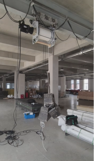


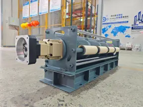
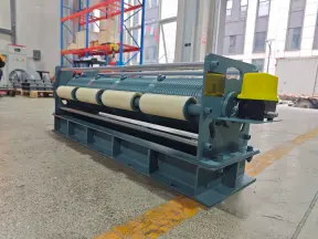
KLD designed a four-rope servo winch to raise and lower a 200 kg car model at four lifting points. All four steel wire ropes wind on one grooved drum, so one motor turns all four winding sections together. A separate rope retainer and a dedicated pulley route for each line help keep it on its intended path. The winch was designed to accept commands from the showroom’s existing control system for timed display sequences.
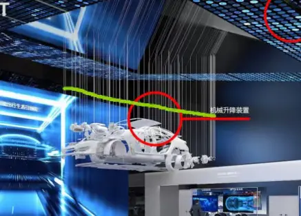
Why a showroom lift needs more than a load rating
The exhibit had to stay level as it moved through a 10 m vertical stroke. If one lifting point traveled farther than another, the model could tilt. The winch also had to fit the available mounting space while routing four ropes to the model’s attachment points.
Those constraints shaped the design together. A winch could meet the load requirement and still be unsuitable if its rope outlets did not line up with the pulley routes or if its controls could not coordinate with the show sequence.
How the four-rope servo winch coordinates lifting
One grooved drum drives all four ropes
KLD arranged the four ropes side by side on separate grooved sections of a single drum. The sections turn through the same angle on every revolution. With matching effective winding diameters, that common rotation gives each rope the same nominal take-up or payout per turn. KLD used a similar drum layout in its four-rope hoisting case for large components.
A common drum coordinates rope movement, but it cannot correct a model that starts out of level. The installed system still needs to be checked with the model attached: initial rope lengths, attachment geometry and unequal loading can affect the height at each lifting point. Define the allowable difference between points before commissioning so the acceptance check has a clear target.
Rope retainers and guide pulleys serve different purposes
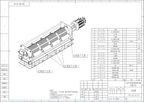
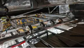
Each rope has its own retaining bar at the drum to help keep it seated in its groove. Beyond the drum, four directional guide pulleys and one corner pulley per rope route the line toward its designated vertical drop. The retaining bars constrain the ropes at the drum; the pulleys set the route through the installation.
KLD used an in-line winch layout to fit the available space. For a similar exhibit, review the winch footprint and the full pulley layout on the same drawing, including access for inspection. The winch may fit on its own while leaving too little room for a workable rope path. For a related indoor application, see KLD’s four-rope stage batten winch.
How the winch connects to the showroom controls
An Inovance servo motor drives the common drum. The client’s central control system was the designated interface for scheduling the model’s ascent and descent as part of the display. The project also specified a travel limit device.
For a similar project, agree on the control interface before finalizing the equipment: which controller sends motion commands, what status the winch returns, and how the sequence responds to a limit or fault. Those details depend on the installation. KLD’s servo winch range includes other configurations for projects with different motion and control requirements.
Showroom winch specifications
| Parámetro | Project specification |
| Suspended exhibit | Car model, approximately 200 kg |
| Rated lifting capacity | 500 kg for the winch system |
| Vertical travel | 10 metros |
| Velocidad de funcionamiento | 5 m/min |
| Specified rope length | 13 m |
| Rope arrangement | Four steel wire ropes on one grooved drum |
| Motor | Inovance servo motor |
| Fuente de alimentación | 380 V, three-phase |
| Control | Interface with the client’s central control system |
| Travel limits | Travel limit device |
What to specify for a similar four-point lift
Share the total suspended weight, including any lifting frame or rigging, and a drawing showing the attachment points and center of gravity. Include the available mounting space, vertical travel, preferred speed and frequency of use. For a timed exhibit, send the intended movement sequence and the central controller’s interface requirements.
If the project uses several winches instead of one common drum, see KLD’s six-point automotive lifting case for an example of a system that uses position feedback to coordinate separate drives.
Have a layout or an exhibit drawing? Share your project requirements with KLD so the team can review the rope routing, mounting envelope and control interface together.
Frequently asked questions
Does a 200 kg exhibit need a 500 kg winch?
The 500 kg rating was specific to this project. For a new exhibit, size the system using the total suspended load, load distribution across the lifting points and the installation’s operating conditions. The project rating alone does not establish a sizing rule for another installation.
Does a single drum guarantee that all four lifting points stay level?
A shared drum gives the four ropes a common mechanical drive. Actual levelness also depends on how the ropes are installed, the exhibit’s attachment geometry and the loads carried by each line. Verify the relative heights through the intended travel during commissioning.
Why is the rope length longer than the lift travel?
Lift travel measures how far the exhibit moves vertically. Rope length also has to account for the route from the drum through the guide pulleys to the load, as well as the rope that must remain on the drum. Confirm the required length from the final layout.